
System Components / Castel
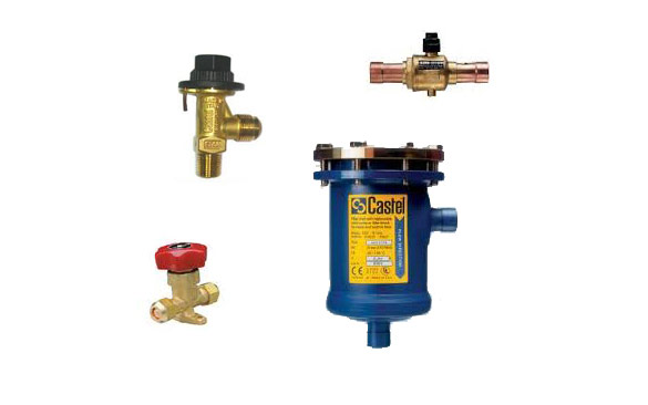
Ball Valve
The specific design of Castel ball valves:
– ensures the internal equilibrium of pressures when the valve is closed
– permits the bi-directional flow of the refrigerant and, consequently, the assembly on the plant without taking into account the direction of the refrigerant
– prevents any risk of ejection or explosion of the spindle.
Models:
6590/...
- •5/8''
- •7/8''
- •1 1/8''
- •1 3/8''
- •1 5/8''
- •2 1/8''
- •2 5/8''
- •3 1/8''
Safety/Shutt off Valves
The valves are standard type, unbalanced, direct-loaded safety valves. Valve opening is produced by the thrust the fluid under pressure exerts on the disc, when said thrust exceeds, under setting conditions, the opposing force of the spring acting on the disc. The stop-shut off valves are designed for installation on commercial refrigerating systems and on civil and industrial conditioning plants, which use friendly refrigerant fluids
Models:
- •3030/...
- •6010/...
- •6110/...
- •6120/...
- •6210/...
Separators
The oil separators, shown in this chapter, are classified “Pressure vessels” in the sense of the Pressure Equipment Directive 97/23/EC, Article 1, Section 2.1.1 and are subject of Article 3, Section 1.1 of the same Directive. They are designed for installation on commercial refrigerating systems and on civil and industrial conditioning plants, which use refrigerant fluids proper to the Group II (as defined in Article 9, Section 2.2 of Directive 97/23/EC and referred to in Directive 67/548/EEC). The advantages of the oil separator on the discharge line of a compressor in a refrigeration system are confirmed by many years of experience. The oil separator intercepts the oil mixed with compressed gas and returns it to the crankcase of the compressor thus assuring an efficient lubrication of its moving parts. Furthermore, the oil separator maintains a high coefficient of condenser and evaporator performance by almost completely removing oil deposits from their exchange surfaces. When a very high temperature at the end of the compression stage leads to the formation of oil vapours, a separator with a capacity exceeding the values shown in the table should be used. Moreover, the oil separator, damping the valves pulsations, reduces system noise with an open or semi-hermetic compressor.
Models:
- •5540/4
- •5540/5
- •5540/7
- •5540/9
- •5540/11
- •5540/13
- •5540/M42
- •5540/17
- •5520/C
- •5520/D
- •5520/E
Liquid line filters
They are designed for installation on commercial refrigerating systems and on civil and industrial conditioning plants, which use refrigerant fluids proper to the Group II . In the case of filters with more than one block, the passage of the fluid takes place in parallel; as a result, the pressure drop does not increase proportionately to the number of blocks. A large ring between the block and the inner surface of the filter permits the accumulation of solid particles, and prevents clogging. Before leaving the filter, the refrigerant fluid must pass through the mesh sieve on which blocks are mounted. The danger that small particles of dehydrating material being introduced into the system is thus avoided. Furthermore, at filter outlet, a plastic cup, the edge of which closely adheres to the inner surface of the filter, prevents dirt from reaching the outlet connection during normal operation and block change.
Models:
- •4411/5A
- •4411/7A
- •4411/9A
- •4411/11A
- •4411/13A
- •4411/17A
- •4412/7A
- •4412/9A
- •4412/11A
- •4412/17A
- •4413/11A
- •4413/13A
- •4414/13A
- •4414/17A
- •4423/17A
- •4423/21A
- •4423/25A
- •4424/25A
- •4424/33A